How to Read and Calculate Welder Duty Cycle: A Practical Guide
Duty cycle is the essential parameter to prevent welder overheating. This guide explains how to interpret rating plate data and safely manage operating times.
In short
- The duty cycle indicates the percentage of time, within a 10-minute interval, that a welder can continuously deliver current before overheating.
- This parameter is measured at a standard temperature of 40 °C in compliance with the European standard EN 60974-1.
- A welder with a 60% duty cycle at 100 A can weld continuously for 6 minutes and must rest for the remaining 4 minutes.
- Exceeding thermal limits triggers the machine's automatic protection, temporarily interrupting the welding current erogation.
Choosing and correctly using a power source for Saldatura ad arco or Taglio plasma requires a thorough understanding of its thermal specifications. The duty cycle represents the primary operating limit to prevent permanent damage to internal components caused by heat generated via the Joule effect.
Monitoring Tools and Materials
To properly manage duty cycles in a maker workshop, complex devices are not required, but it is advisable to have: - A manual or digital stopwatch to monitor arc-on time. - Strumenti di misura digitali, such as an infrared thermometer, useful for checking the external chassis temperature on machines without a digital display.
What Does the Duty Cycle Percentage Indicate?
The duty cycle percentage indicates how many minutes, within a standard 10-minute window, the machine can deliver a specific current before thermal cutout occurs. If a welding machine shows a rating of 35% at 150 A, it means you can weld continuously for 3.5 minutes at that current intensity, after which the power source will require a 6.5-minute pause in standby mode to allow the circuits to cool down properly.
How to Read the EN 60974-1 Data Table on a Welder?
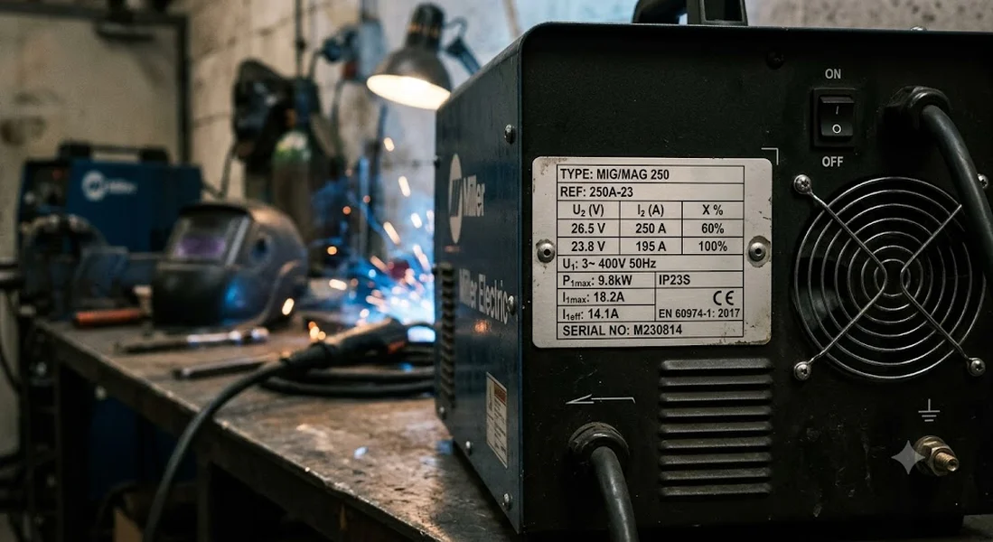
The EN 60974-1 data table on the technical specification plate is read by crossing the values of row X (duty cycle) with rows I₂ (welding current) and U₂ (conventional arc voltage). European manufacturers are required to declare this data based on tests conducted in a climate chamber at a fixed ambient temperature of 40 °C. If tests were conducted at lower temperatures, as often happens with cheap, non-standard products, the declared duty cycle would appear falsely higher.
A typical data matrix found on a mid-range inverter power source is shown below:
| Parameter | Configuration 1 | Configuration 2 | Configuration 3 |
|---|---|---|---|
| X (Duty cycle) | 35% | 60% | 100% |
| I₂ (Delivered current) | 160 A | 120 A | 95 A |
| U₂ (Working voltage) | 26.4 V | 24.8 V | 23.8 V |
Analyzing this table shows that as the required current (I₂) decreases, the continuous operation capacity increases, reaching 100% at 95 A. This means that at 95 A, the welder can operate without any time interruption.
What Is the Difference Between Hobby and Professional Use?
The main difference lies in the machine's ability to maintain high duty cycles at significant amperages without interrupting the maker's activity. Inexpensive power sources designed for hobby use often have a low duty cycle (frequently below 20% at maximum power), forcing the operator into long waits even when executing medium-length weld beads. On the contrary, professional systems integrate more efficient transformers and ducted forced ventilation systems that guarantee a 60% or 100% cycle at high currents.
This classification of thermal capabilities applies in a similar way to technological variants such as the Saldatrice a punti (spot welding) or instruments used in Saldatura elettronica, although in the latter, the power involved is lower and rest times are primarily dictated by managing the soldering tip.
Safety and Thermal Management During Work
The safety of internal components depends entirely on the operator's behavior when the thermal protection is activated, usually signaled by a yellow light turning on the front panel. When the machine enters lockout mode, the main power switch must never be turned off. Turning off the power source would immediately stop the cooling fan as well, trapping heat inside the chassis and risking damage to sensitive electronic components like IGBT modules. The correct procedure is to leave the machine turned on and idle, allowing the forced airflow to quickly lower the internal temperature until the indicator light goes out.
For further insights into operating parameter settings and execution techniques, you can consult the Tecniche & tutorial section of our magazine.