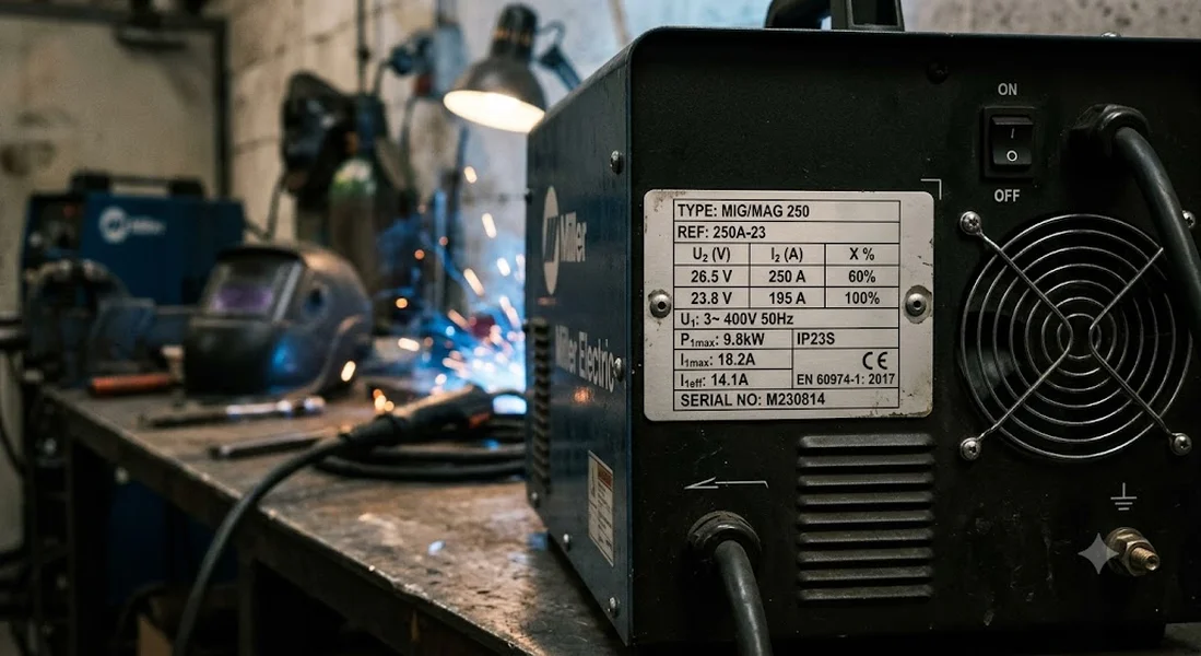
MIG/MAG welding: how to choose wire diameter, amperage and material thickness
Wire diameter, current and workpiece thickness are chosen together, not separately. A practical guide to reading the parameters of a MIG/MAG welder and knowing which wire to use for any sheet metal.
In brief
- The three parameters — wire diameter, amperage and material thickness — are linked: they are chosen together, not one at a time.
- Rule of thumb for mild steel in the flat position: about 1 ampere for every 0.025 mm of thickness (≈ 40 A per mm). It holds up to about 6 mm, beyond which you need a prepared joint and multiple passes.
- Typical diameters for makers: 0.8 mm for thin sheet (0.6–3 mm), 1.0 mm the most versatile size, 1.2 mm for thicknesses from about 3 mm up.
- The current windows of the various diameters overlap: at 180–250 A both a 1.0 mm and a 1.2 mm wire are usable. The choice depends on position, fit-up and the desired speed.
- The values change with the shielding gas, the welding position and the transfer mode. The tables give a starting point, not a fixed setpoint.
The question "which wire do I use?" has no single answer, because in arc welding the wire diameter is not chosen in isolation. It is the central link in a chain that starts from the thickness of the workpiece and ends at the current to set. Getting one link wrong shifts all the others: a wire too thick on thin sheet means burn-through; a wire too fine on thick steel means insufficient penetration and beads that sit on top without fusing.
In this article we line up the three variables and explain how to read them together. The values we report are starting points drawn from rules well established in practice and from the current windows indicated by manufacturers; they do not replace your machine's manual or the qualification of a procedure, where required.
The three variables that hold together
The wire in MIG/MAG is at once the electrode and the filler material. This indissolubly links three quantities:
- Material thickness: how much heat is needed to fuse the workpiece without burning through it or leaving it cold.
- Amperage: in the MIG process the current is governed by the wire feed speed. More wire per minute, more current, more heat deposited.
- Wire diameter: it defines the current window within which the arc stays stable. Below the minimum threshold the arc is unstable; above the maximum the wire burns back to the tip.
The key point: thickness dictates how much heat is needed, the heat translates into current, and the current must fall within the window of the chosen diameter. This is why you always start from thickness.
Which wire diameter for which thickness?
The short answer: 0.8 mm for thin sheet up to about 3 mm, 1.0 mm as the most versatile size for most work, 1.2 mm and above for thicknesses from about 3 mm up. The diameters share wide zones of overlap, so more than one choice is often correct.
| Wire diameter | Indicative steel thickness | Typical use |
|---|---|---|
| 0.6 mm | 0.6–1.5 mm | Auto body, thin sheet, precision work |
| 0.8 mm | 0.6–3 mm | Thin sheet, panels, light fabrication |
| 1.0 mm | ~1–6 mm | The most versatile size: frames, brackets, most fabrication |
| 1.2 mm | from ~3 mm up | Structural fabrication, medium-to-high thicknesses |
The 1.0 mm is the one with the widest useful window: in practice it covers from about 80 A up to over 250 A on a well-tuned machine, which is why it remains the default choice for those who do not want to keep changing the spool.
How many amps for the material thickness?
For mild steel in the flat position, a well-established rule taken up by numerous technical sources is about 1 ampere for every 0.025 mm of thickness — equivalent to about 40 A per millimetre, or 1 ampere for every thousandth of an inch. A 3 mm sheet therefore requires roughly around 120 A as a starting point.
| Steel thickness | Indicative current | Recommended wire diameter |
|---|---|---|
| 1 mm | ~40 A | 0.6–0.8 mm |
| 2 mm | ~80 A | 0.8–1.0 mm |
| 3 mm | ~120 A | 0.8–1.0 mm |
| 4 mm | ~160 A | 1.0–1.2 mm |
| 5 mm | ~200 A | 1.0–1.2 mm |
| 6 mm | ~240 A | 1.2 mm |
This linear proportion holds well up to about 6 mm. Beyond that, the relationship "stops applying": on greater thicknesses you do not simply increase the current, you prepare the joint (bevel, fit-up) and work with multiple passes. It is a recognised limit of the rule, not a detail: anyone applying it at 10 mm is making a mistake.
Why do the current windows overlap?
Because each diameter has a wide operating range, not a single value, and those ranges overlap. At 180–250 A, for example, both a 1.0 mm and a 1.2 mm wire are usable on the same workpiece. The choice between the two depends on factors the table does not capture:
- Welding position: vertical or overhead, a finer wire (0.8–1.0 mm) gives more control and less spatter.
- Fit-up and gaps: with gaps or uneven thicknesses the finer, more forgiving wire is preferable.
- Speed: at equal thickness, the thicker wire deposits more material per minute, so it travels faster on well-fitted joints in the flat position.
When two options both fall within the window, there is no absolute "right" choice: there is the one best suited to your joint.
The variables that shift everything
The tables hold as a starting point for mild steel with a standard setup. Four factors shift the numbers and must always be considered:
- Shielding gas: pure CO₂ penetrates more but generates more spatter; argon/CO₂ mixtures (for example 80/20) give a cleaner arc at equal current. Changing the gas changes the arc's behaviour.
- Transfer mode: short-arc (short circuit) is typical of thin thicknesses and low currents; spray-arc works at higher currents on thick material. They are distinct regimes, not a linear continuum.
- Material: the numbers above hold for carbon steel. Stainless uses dedicated wires (such as ER308L for 304); aluminium requires softer wires (ER4043, ER5356), often a spool gun torch, and conducts heat differently, so it needs more current at equal thickness.
- Position: in the flat position you can push; out of position you lower the current to control the pool.
It is the section that separates a copied table from a conscious choice: the values are an initial reference, to be fine-tuned on the test piece.
A practical procedure
In our editorial work the approach that works is always the same: start from the thickness, derive the current, check that it falls within the window of the wire fitted, then fine-tune on a scrap identical to the workpiece. Never on the good component. The detailed operating steps are gathered in the steps section of this tutorial.
For those who want to frame the process within the broader context of joining techniques, we gather related guides in the Techniques & tutorials section of the magazine.
Safety
Arc welding involves real risks: intense optical radiation (you need a mask with an adequate protection grade and skin protection), metal fumes (adequate extraction or ventilation, particularly with stainless and galvanised materials), risk of fire and burns. Do not weld on containers that have held flammable substances without remediation. Always check the earthing of the workpiece and the integrity of cables and torch before starting.