Lathe Anatomy: A Complete Guide to Component Nomenclature
Bed, headstock, tailstock, carriage and slides: every lathe component has a precise name and a specific function. A practical guide to nomenclature for choosing, maintaining, and communicating in the workshop.
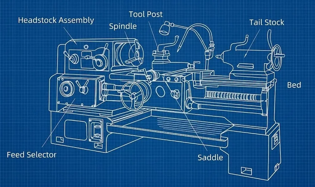
In brief - The cast-iron bed is the load-bearing structure: it absorbs cutting forces and ensures alignment between headstock and tailstock. - The headstock houses the spindle and speed change mechanism; the tailstock supports the free end of the workpiece. - The carriage (longitudinal, cross, and compound slides) controls tool movement with micrometric precision. - The lead screw transmits motion for threading; the feed rod handles cylindrical turning. - Knowing the exact name of each part is the first step to reading a manual, ordering a spare part, and communicating in the workshop without ambiguity.
Introduction
Anyone approaching turning for the first time faces a machine that, in essence, has not changed radically since the nineteenth century: a workpiece rotates, a tool removes material. Behind that apparent simplicity lie dozens of mechanical sub-assemblies, each with a precise name and a well-defined function. Knowing this nomenclature is essential for reading an operator's manual, ordering the right spare part, and communicating with other machinists unambiguously.
This guide covers the components of a conventional engine lathe — the most common type found in maker labs and small workshops. Variants (vertical lathe, turret lathe, CNC lathe) share most of the basic terminology.
Useful tools for following this guide
- Your lathe's manual (every manufacturer provides a numbered exploded-view drawing)
- A vernier caliper or micrometer to verify the dimensions mentioned
- Allen keys and open-end wrenches to remove guards and observe the internal mechanisms
The bed
The bed is the load-bearing structure of the entire lathe, almost always made of grey cast iron for its vibration-damping capacity and long-term dimensional stability.
On the upper face run the ways, ground surfaces on which the carriage and tailstock slide:
- Prismatic ways (V-shaped or trapezoidal): natural self-centring and good resistance to lateral loads.
- Flat ways: simpler to manufacture, require more frequent adjustment.
A bed with worn ways produces tapered parts instead of cylindrical ones: it is the first component to inspect when accuracy drops. The bed rests on adjustable feet: levelling that is off by even a few hundredths of a millimetre introduces systematic errors.
The headstock
The headstock, fixed at the left end of the bed, is the kinematic heart of the lathe. It contains:
- Spindle: a hollow shaft mounted on precision bearings, with an internal taper (typically Morse or metric) and a threaded flange.
- Speed change mechanism: gears or stepped pulleys to vary RPM; on more recent models, a continuously variable drive.
- Reverse lever: reverses the direction of rotation for threading operations.
The self-centring chuck
The chuck clamps the workpiece in rotation:
| Type | Jaws | Typical use |
|---|---|---|
| 3-jaw self-centring | 3 | Cylindrical and hexagonal parts. Automatic centring. |
| 4-jaw independent | 4 | Irregular or eccentric parts. Individual jaw adjustment. |
For irregularly shaped parts, faceplates — flat plates with T-slots — are used.
The tailstock
The tailstock, at the right end of the bed, slides along the ways and serves two functions:
- Workpiece support: via a centre (live or dead) fitted in the quill.
- Auxiliary tool holder: the quill can hold drill bits, reamers, or taps for axial drilling.
The quill is a sliding cylinder with an internal Morse taper, operated by a handwheel. Misalignment between tailstock and headstock is a frequent cause of taper errors.
The carriage and slides
The carriage is the moving assembly that carries the tool along the workpiece. It consists of three stacked sub-assemblies:
Longitudinal slide: travels along the bed ways, parallel to the axis. Movement is manual (handwheel) or power-driven (feed rod or lead screw).
Cross slide: perpendicular to the axis, controls the depth of cut. Note: the graduated dial typically reads the diameter removed, not the radius.
Compound slide (swivelling): rotates on a pivot to turn short tapers, for finishing operations, and for angled-infeed threading.
The apron
The apron is the front face of the carriage. It houses the gears and clutches that convert feed-rod or lead-screw rotation into linear carriage motion. Typical controls on the apron:
- Longitudinal feed lever
- Cross feed lever
- Half-nut lever for engaging the lead screw
- Manual handwheel
The tool post
The tool post, mounted on the compound slide, holds the cutting tool. Main types:
- Quick-change tool post: tool swap in seconds with a preset centre-height.
- Four-position turret: rotating block with four tool stations.
- Single tool holder: the simplest type, one tool clamped by screws.
Tool height relative to the lathe centre is a critical parameter: a tool set too high or too low produces poor finishes and, in the worst case, can break the insert.
Lead screw and feed rod
Two shafts run parallel to the bed on the front side:
- Lead screw: a precision trapezoidal screw used exclusively for threading. The carriage engages via the half-nut.
- Feed rod: a keyed shaft for cylindrical turning and facing.
The feed gearbox (Norton gearbox), with its selector levers, sets the feed rate in mm/rev and, for threading, the thread pitch.
Accessories and auxiliary components
Steady rests
Steady rests support long, slender workpieces prone to deflection:
- Fixed steady rest: clamped to the bed with three adjustable jaws or rollers.
- Follow rest: mounted on the carriage, it follows the tool, supporting the workpiece at the point of machining.
Drive devices
For workpieces mounted between centres, a lathe dog — a collar with a tail that engages a drive plate — is used.
Operational safety
Nomenclature has a direct practical bearing on safety:
- Do not confuse the half-nut lever with the feed lever: engaging the half-nut during normal turning can damage the lead screw.
- Chuck jaws protrude beyond the faceplate diameter: never leave the chuck key inserted and never approach with loose clothing.
- The tailstock quill must always be locked after positioning: a free quill can retract under load.
- Safety guards, safety micro-switches, spindle brake, and emergency stop button (red mushroom) are mandatory on modern lathes.
Final notes
This guide covers the standard nomenclature of a conventional engine lathe. CNC lathes add specific components — encoders, servo motors, automatic turrets, centralised lubrication systems — that deserve a dedicated treatment. For those approaching CNC milling, many concepts (ways, slides, ball screws) reappear with analogous functions.
The terminology adopted here follows current usage. In workshops it is common to encounter local terms or anglicisms; wherever possible, we have indicated the corresponding term in parentheses to facilitate consultation of international manuals and catalogues.